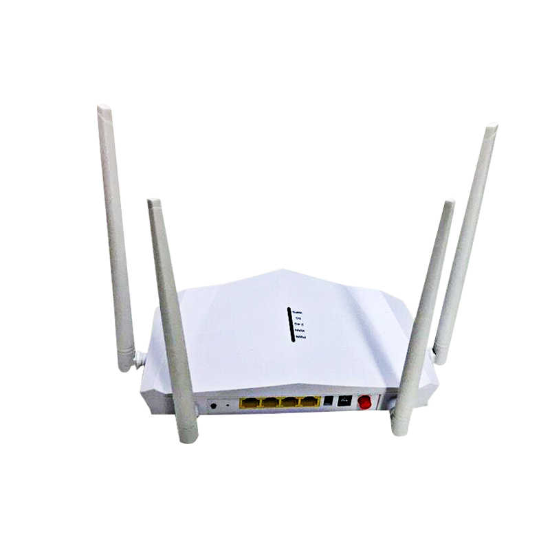
Equipamento de transmissão HFC: Garantir redes confiáveis híbridas-fibra-coaxiais
Introduction to HFC Transmission Equipment
In the modern digital landscape, reliable and high-speed broadband connectivity is not just a luxury but a fundamental necessity. From streaming high-definition video to facilitating remote work and education, our reliance on robust network infrastructure continues to grow. For decades, Hybrid Fiber-Coaxial (HFC) networks have served as the backbone for delivering these essential services to millions of homes and businesses worldwide. The strategic combination of high-capacity fiber optics and the extensive reach of coaxial cable makes HFC a powerful and cost-effective solution for broadband deployment.
1.1. What is HFC (Hybrid Fiber-Coaxial) Technology?
HFC technology, as its name suggests, is a telecommunications network architecture that integrates both fiber optic cables and coaxial cables. The network typically originates from a central headend or central office, where high-bandwidth digital signals are converted into optical signals and transmitted over fiber optic lines. These fiber lines extend deep into neighborhoods, connecting to optical nodes. At these nodes, the optical signals are converted back into radio frequency (RF) electrical signals, which are then distributed to individual subscribers via existing coaxial cable infrastructure. This hybrid approach leverages the superior bandwidth, low loss, and noise immunity of fiber for long-haul transmission, while utilizing the ubiquitous and cost-effective coaxial plant for the "last mile" connection to homes.
1.2. Importance of Reliable Transmission Equipment in HFC Networks
The performance and stability of an HFC network are directly dependent on the reliability and quality of its transmission equipment. Every component, from the initial signal generation at the headend to the final delivery at the subscriber's modem, plays a critical role. Faulty or underperforming equipment can lead to a cascade of issues, including:
Service Interruptions: Dropped internet connections, pixelated television, and garbled voice calls directly impact user experience and can lead to customer churn.
Reduced Bandwidth and Speed: Impaired signal quality can significantly degrade the effective data rates, preventing subscribers from accessing the high speeds they expect.
Increased Latency: Poorly managed signals can introduce delays, impacting real-time applications like online gaming and video conferencing.
Higher Operational Costs: Frequent troubleshooting, truck rolls, and equipment replacements due to unreliable components can be a significant drain on an operator's resources.
Customer Dissatisfaction: Ultimately, an unreliable network leads to frustrated customers and a damaged reputation.
Therefore, investing in high-quality, robust HFC transmission equipment and implementing stringent maintenance protocols are paramount to ensuring a dependable and high-performance network that meets the evolving demands of today's digital consumers.
1.3. Overview of Key Components
An HFC network is a complex ecosystem of interconnected devices, each contributing to the seamless flow of data. While we will delve into each in more detail, the primary components of HFC transmission equipment include:
Optical Nodes: The critical interface where optical signals from the fiber backbone are converted to RF signals for the coaxial network, and vice-versa.
RF Amplifiers: Devices strategically placed within the coaxial plant to boost signal strength and compensate for attenuation over distance.
CMTS (Cable Modem Termination System) / CCAP (Converged Cable Access Platform): The intelligent headend equipment responsible for managing data traffic between the internet backbone and the HFC access network, communicating with subscriber cable modems.
These components, along with the sophisticated systems for signal monitoring and management, collectively ensure the robust and efficient operation of hybrid fiber-coaxial networks.
Okay, let's continue with the next section of your article: "Key Components of HFC Transmission Equipment."
Key Components of HFC Transmission Equipment
To truly appreciate the reliability of an HFC network, it's essential to understand the individual components that make it work. These pieces of equipment are meticulously engineered to handle complex signal processing, ensuring data, video, and voice services reach subscribers with optimal quality.
2.1. Optical Nodes
The optical node is arguably the most critical piece of equipment in the HFC network, serving as the bridge between the high-capacity fiber optic backbone and the widespread coaxial distribution plant.
2.1.1. Function and Role in HFC Networks
An optical node's primary function is optical-to-electrical (O/E) and electrical-to-optical (E/O) conversion.
Forward Path (Downstream): It receives modulated optical signals from the headend via the fiber optic cable. Inside the node, an optical receiver converts these optical signals into RF electrical signals. These RF signals, carrying television channels, internet data, and voice, are then amplified and launched onto the coaxial distribution network towards subscribers.
Return Path (Upstream): Conversely, for upstream communication (e.g., subscriber internet uploads, remote control signals), the optical node receives RF electrical signals from the coaxial network. An optical transmitter within the node converts these RF signals back into optical signals, which are then sent back to the headend over dedicated return path fibers.
The optical node effectively defines the serving area of a coaxial segment, known as a Fiber Node Serving Area (FNSA). Its strategic placement allows for the division of large service areas into smaller, more manageable segments, optimizing signal quality and enabling better bandwidth utilization.
2.1.2. Types of Optical Nodes
Optical nodes have evolved significantly to meet increasing bandwidth demands and facilitate new architectural approaches:
Standard (Analog) Optical Nodes: These are the traditional nodes that perform direct analog O/E and E/O conversions. While still in use, their limitations in supporting higher bandwidth and advanced modulation schemes have led to their gradual replacement.
Digital Optical Nodes: These nodes digitize the RF signals before converting them to optical for transmission over fiber. This approach offers superior signal quality and resistance to noise over longer distances.
Remote PHY (Physical Layer) Nodes: A key component of Distributed Access Architectures (DAA), Remote PHY nodes move the DOCSIS PHY layer processing from the headend out to the node. This reduces the analog optical path, improves signal performance, and allows for more efficient use of spectrum.
Remote MACPHY Nodes: Taking DAA a step further, Remote MACPHY nodes move both the DOCSIS Media Access Control (MAC) and Physical (PHY) layers out to the node, making the node essentially a mini-CMTS. This offers even greater benefits in terms of latency, capacity, and operational simplicity.
2.1.3. Key Features and Specifications
When evaluating optical nodes, several key features and specifications are critical:
Optical Input Power Range: The range of optical power (in dBm) the receiver can effectively handle.
RF Output Level (Downstream): The maximum RF output power (in dBmV) the node can deliver onto the coaxial network.
RF Input Level (Upstream): The range of RF input power (in dBmV) the upstream optical transmitter can accept.
Operating Frequency Range: The spectrum of frequencies (e.g., 5-85 MHz for upstream, 54-1002 MHz or higher for downstream) the node supports. With DOCSIS 4.0, this is extending to 1.2 GHz, 1.8 GHz, or even 3 GHz.
Gain Control: Both manual and automatic gain control (AGC) features to maintain consistent signal levels despite fluctuations in input power.
Return Path Capabilities: The number of return path transmitters and their specifications (e.g., bandwidth, power).
Remote Monitoring and Management: The ability to remotely monitor node performance, adjust settings, and diagnose issues, which is crucial for efficient network operation.
Modularity and Scalability: The design should allow for easy upgrades and expansion (e.g., adding more return path transmitters, changing modules for DAA upgrades).
2.2. RF Amplifiers
As RF signals travel through coaxial cables, they experience signal loss, or attenuation, due to the inherent resistance and capacitance of the cable. RF amplifiers are essential active devices strategically placed in the coaxial distribution network to overcome this loss and maintain adequate signal strength for subscribers.
2.2.1. Purpose of RF Amplifiers
The primary purpose of an RF amplifier is to boost the strength of the RF signal in both the forward (downstream) and, in most modern two-way HFC networks, the return (upstream) paths. Without amplification, the signal would quickly degrade to an unusable level over distance, leading to poor picture quality, slow internet speeds, and unreliable voice services. Amplifiers essentially "recharge" the signal, ensuring it remains strong enough to reach the end-user's equipment.
2.2.2. Different Types of Amplifiers (e.g., Line Extenders, Bridger Amplifiers)
RF amplifiers come in various configurations, each designed for specific roles within the coaxial network:
Bridger Amplifiers: These are typically located closer to the optical node, where the primary distribution feeder lines branch out. They are designed with multiple outputs to feed different coaxial branches and often incorporate diplex filters to separate forward and return path signals. They usually have higher gain and more sophisticated internal components than line extenders.
Line Extender Amplifiers: These amplifiers are placed further down the coaxial feeder lines, beyond bridger amplifiers. They have fewer outputs (often one input, one output) and are designed to provide additional gain to compensate for signal loss over long cable runs to reach individual neighborhoods or street segments.
Push-Pull Amplifiers: An older design, push-pull amplifiers use two transistors in a push-pull configuration to reduce even-order distortion, improving signal linearity.
Power Doubling Amplifiers: These amplifiers employ a technique that combines two push-pull amplifier stages in parallel, effectively "doubling" the output power and linearity, leading to lower distortion and higher output levels.
Gallium Arsenide (GaAs) Amplifiers: Modern amplifiers frequently utilize GaAs technology for their active components. GaAs transistors offer superior performance compared to traditional silicon, providing higher gain, lower noise figures, and better linearity, especially at higher frequencies.
Gallium Nitride (GaN) Amplifiers: Representing the latest advancement, GaN amplifiers offer even higher power output, efficiency, and linearity than GaAs, making them ideal for next-generation HFC networks supporting DOCSIS 3.1 and 4.0's extended spectrum capabilities.
2.2.3. Gain, Noise Figure, and Linearity
Three crucial parameters define the performance of an RF amplifier:
Gain: Measured in decibels (dB), gain is the amount by which an amplifier increases the signal strength. An amplifier with a gain of 20 dB will multiply the input signal's power by 100. Adequate gain is essential, but too much can lead to signal clipping and distortion.
Noise Figure (NF): Also measured in decibels (dB), the noise figure quantifies the amount of noise an amplifier adds to the signal. Every electronic component generates some internal noise. A lower noise figure is always desirable, as added noise accumulates throughout the network and can degrade signal quality, especially for high-frequency digital signals.
Linearity (Distortion): Linearity refers to an amplifier's ability to amplify the signal without introducing new, unwanted frequencies or distorting the original signal''s waveform. Non-linear amplification creates intermodulation distortion (IMD) products, such as Composite Second Order (CSO) and Composite Triple Beat (CTB) distortion for analog video, and introduces noise-like impairments that affect digital signal integrity (e.g., error vector magnitude - EVM). High linearity is crucial for maintaining the quality of complex modulated signals used in DOCSIS.
Proper amplifier selection, placement, and regular maintenance are vital to ensure optimal signal levels and minimal distortion throughout the HFC distribution network.
2.3. CMTS (Cable Modem Termination System)
While optical nodes and RF amplifiers manage the physical transmission of signals over fiber and coax, the Cable Modem Termination System (CMTS), or its more advanced successor, the Converged Cable Access Platform (CCAP), is the intelligent core that enables data communication within the HFC network. Located at the headend or central office, the CMTS/CCAP acts as the gatekeeper and traffic controller for broadband internet services.
2.3.1. Role of CMTS in Data Transmission
The CMTS serves as the interface between the cable operator's IP (Internet Protocol) network (which connects to the broader internet) and the HFC access network that reaches subscribers' homes. Its primary roles in data transmission include:
Downstream Data Transmission: The CMTS takes IP data packets from the internet backbone, modulates them into RF signals, and sends them downstream through the HFC plant to subscriber cable modems. It allocates bandwidth, schedules data, and manages Quality of Service (QoS) for various traffic types.
Upstream Data Reception: It receives RF signals carrying upstream data packets (uploads) from subscriber cable modems. The CMTS then demodulates these RF signals, converts them back into IP packets, and forwards them to the internet.
Modem Registration and Provisioning: When a subscriber's cable modem is connected and powered on, it communicates with the CMTS to register on the network, obtain an IP address, and receive configuration files for service activation.
Traffic Management and Security: The CMTS is responsible for managing bandwidth allocation, prioritizing different types of traffic (e.g., voice, video, data), and implementing security measures to prevent unauthorized access and ensure data privacy.
Channel Bonding: Modern CMTS units utilize channel bonding, allowing multiple downstream and upstream channels to be grouped together. This significantly increases the available bandwidth for each subscriber, enabling multi-gigabit speeds.
In essence, the CMTS acts as a specialized router and modem bank, facilitating two-way communication between millions of internet users and the global internet.
2.3.2. Key Features and Capabilities
Modern CMTS/CCAP platforms are highly sophisticated devices packed with advanced features and capabilities to meet the demands of contemporary broadband services:
High-Density Port Capacity: Capable of supporting thousands to tens of thousands of subscribers on a single platform, with numerous RF ports for connecting to the HFC plant.
Multi-DOCSIS Standard Support: Compatibility with various DOCSIS standards (e.g., DOCSIS 3.0, 3.1, and increasingly 4.0), allowing operators to seamlessly upgrade their networks and offer higher speeds.
Advanced Modulation Schemes: Support for complex modulation techniques like 256-QAM (Quadrature Amplitude Modulation) and 1024/4096-QAM, which pack more data into each hertz of spectrum, dramatically increasing throughput.
Orthogonal Frequency-Division Multiplexing (OFDM/OFDMA): Key to DOCSIS 3.1 and 4.0, OFDM/OFDMA allows for more efficient use of spectrum, improved spectral efficiency, and better performance in noisy environments.
Distributed Access Architecture (DAA) Integration: Modern CCAPs are designed to integrate with Remote PHY and Remote MACPHY devices, enabling the move of processing closer to the edge of the network. This involves supporting digital optical interfaces (e.g., Ethernet, Remote PHY Interface - R-PHY) rather than traditional analog RF outputs.
Integrated Routing and Switching: Often include robust routing and switching capabilities to handle vast amounts of IP traffic.
QoS (Quality of Service) Mechanisms: Tools to prioritize different types of network traffic, ensuring that latency-sensitive applications like VoIP and video conferencing receive preferential treatment.
Security Features: Built-in firewalls, authentication protocols (e.g., BPI ), and encryption to protect the network and subscriber data.
Remote Management and Monitoring: Comprehensive tools for remote configuration, performance monitoring, troubleshooting, and software upgrades, essential for large-scale network operations.
Energy Efficiency: Design considerations for lower power consumption, aligning with environmental goals and reducing operational costs.
2.3.3. DOCSIS Standards Supported
The evolution of the CMTS/CCAP is intrinsically linked to the development of DOCSIS standards. Each new DOCSIS iteration pushes the boundaries of HFC network capabilities, and the CMTS/CCAP must support these standards to unlock the higher speeds and efficiencies they offer.
DOCSIS 1.x/2.0: These earlier standards laid the foundation for broadband over cable, offering initial broadband speeds and basic QoS. Legacy CMTS units would support these.
DOCSIS 3.0: A significant leap forward, DOCSIS 3.0 introduced channel bonding, allowing multiple downstream and upstream channels to be combined. This enabled speeds in the hundreds of megabits per second (Mbps). Most active CMTS units today support DOCSIS 3.0.
DOCSIS 3.1: This standard further revolutionized HFC by introducing OFDM/OFDMA modulation, significantly higher-order QAM (1024-QAM, 4096-QAM), and improved error correction. DOCSIS 3.1 enables gigabit-plus speeds (often 1 Gbps downstream and 50-100 Mbps upstream or more) and better spectral efficiency. A CMTS/CCAP supporting DOCSIS 3.1 is crucial for offering these higher-tier services.
DOCSIS 4.0: The latest evolution, DOCSIS 4.0, is designed to enable multi-gigabit symmetrical speeds (e.g., 10 Gbps downstream and 6 Gbps upstream). It achieves this through Full Duplex DOCSIS (FDX), which allows simultaneous upstream and downstream transmission over the same spectrum, and Extended Spectrum DOCSIS (ESD), which expands the usable frequency range on the coaxial cable to 1.8 GHz or even 3 GHz. CCAPs supporting DOCSIS 4.0 are at the forefront of HFC technology, paving the way for next-generation services.
The capabilities of the CMTS/CCAP are paramount in determining the speed, reliability, and service offerings of an HFC network. As bandwidth demands continue to soar, the continuous advancement of these platforms, in line with evolving DOCSIS standards, remains critical for the longevity and competitiveness of HFC technology.
3. Understanding Forward and Return Paths
Unlike traditional telephony or simple point-to-point data links, HFC networks operate with two distinct communication paths: the forward path (downstream) and the return path (upstream). These paths utilize different frequency spectrums within the coaxial cable to enable simultaneous two-way communication between the headend and the subscriber. This separation is key to the efficiency and functionality of HFC technology.
3.1. Forward Path (Downstream)
The forward path, also known as the downstream path, carries signals from the cable operator's headend or central office to the subscriber's premises. This is the path responsible for delivering most of the content and data that consumers receive.
3.1.1. Signal Transmission from Headend to Subscribers
The journey of a downstream signal begins at the headend with the CMTS/CCAP for data and voice, and video processing systems for television signals.
Signal Generation: Digital data (internet traffic, VoIP), and analog/digital video signals are modulated onto specific radio frequency (RF) carriers.
Optical Conversion: These RF signals are then converted into optical signals by optical transmitters at the headend.
Fiber Distribution: The optical signals travel over high-capacity fiber optic cables to the various optical nodes located in neighborhoods.
O/E Conversion at Node: At the optical node, an optical receiver converts the incoming optical signals back into RF electrical signals.
Coaxial Distribution: These RF signals are then amplified and distributed over the coaxial cable network. Along the way, RF amplifiers boost the signal strength to compensate for attenuation, and splitters/taps distribute the signal to individual homes.
Subscriber Reception: Finally, at the subscriber's premises, devices like cable modems and set-top boxes receive these RF signals, demodulate them, and extract the original data, video, or voice information.
The downstream path is characterized by its broad bandwidth, capable of carrying a vast amount of information, reflecting the high demand for content consumption.
3.1.2. Frequency Allocation
The forward path typically occupies the higher frequency spectrum within the coaxial cable. In traditional HFC networks, the downstream frequency range commonly starts around 54 MHz or 88 MHz and extends upwards, often to 860 MHz or 1002 MHz.
With the advent of DOCSIS 3.1, the downstream spectrum has expanded significantly to support gigabit and multi-gigabit speeds, reaching 1.2 GHz (1218 MHz). The upcoming DOCSIS 4.0 (Extended Spectrum DOCSIS - ESD) pushes this even further, with capabilities extending to 1.8 GHz or even 3 GHz. This expansion allows for more data to be carried, enabling higher throughput and more advanced services. The forward path typically uses a combination of analog modulation (for traditional TV channels) and digital modulation (QAM, OFDM) for data and digital video.
3.2. Return Path (Upstream)
The return path, or upstream path, carries signals from the subscriber's premises back to the headend. This path is crucial for interactive services such as internet uploads, VoIP calls, online gaming, video conferencing, and remote control signals for set-top boxes.
3.2.1. Signal Transmission from Subscribers to Headend
The upstream signal flow is essentially the reverse of the downstream:
Subscriber Origination: A subscriber's cable modem or VoIP equipment generates an electrical signal (e.g., an internet upload request).
RF Modulation: This data is modulated onto a specific RF carrier by the subscriber's equipment.
Coaxial Transmission: The RF signal travels over the coaxial cable network back towards the optical node.
E/O Conversion at Node: At the optical node, the upstream RF signals from all connected subscribers are collected by an RF receiver and then converted into an optical signal by an optical transmitter within the node.
Fiber Transmission: This optical signal travels back over a dedicated return path fiber (or a wavelength-multiplexed fiber) to the headend.
Optical Reception at Headend: At the headend, optical receivers convert the optical signals back into RF electrical signals.
CMTS Reception: Finally, the CMTS/CCAP receives these RF signals, demodulates them, converts them into IP packets, and sends them onto the internet backbone.
The return path faces unique challenges, including noise ingress (unwanted signals entering the coaxial plant from homes) and the need to efficiently manage signals from multiple subscribers simultaneously.
3.2.2. Importance of Return Path Monitoring and Maintenance
The return path is often considered the more challenging path to manage and maintain in an HFC network. Its lower frequency range and the cumulative nature of noise from many subscriber homes make it susceptible to various issues.
Frequency Allocation: The return path typically occupies the lower end of the coaxial spectrum, ranging from 5 MHz to 42 MHz or 5 MHz to 85 MHz (Mid-Split). With DOCSIS 3.1 (High-Split), the upstream spectrum can extend up to 204 MHz, and with DOCSIS 4.0 (Full Duplex DOCSIS - FDX and Ultra-High-Split), it can go even higher, potentially sharing spectrum with the downstream or reaching 684 MHz or even 1.2 GHz.
Noise Ingress: Because lower frequencies are more prone to external interference (e.g., from home appliances, unshielded wiring, ham radios), noise "funnels" from multiple homes into the return path, degrading signal quality. This makes robust shielding and proper grounding critical.
Impulse Noise: Short bursts of high-amplitude noise, often caused by electrical surges or switching, can severely disrupt upstream communication.
Upstream Channel Capacity: The available bandwidth for upstream is generally much smaller than downstream, which is why upload speeds are typically lower than download speeds.
Maintaining Signal Quality: Due to these challenges, continuous and proactive monitoring of the return path is absolutely essential. Technicians use specialized tools like spectrum analyzers and return path monitoring systems to detect noise, signal impairments, and interferences early, allowing for timely intervention and maintenance to ensure reliable upstream connectivity. Effective return path management is key to providing high-quality interactive services and consistent upload speeds for subscribers.
Understanding the distinct characteristics and challenges of both the forward and return paths is fundamental to designing, deploying, and maintaining a high-performing and reliable HFC network.
Let's proceed with the critical aspect of ensuring signal integrity and quality within HFC networks.
4. Ensuring Signal Integrity and Quality
The performance of an HFC network is ultimately measured by the quality of the signal delivered to the subscriber. Signal integrity refers to the accuracy and clarity of the transmitted information. Maintaining high signal integrity is paramount, as even minor degradations can lead to service disruptions, reduced speeds, and a poor user experience. This section explores the common factors that compromise signal quality and the techniques used to monitor and mitigate them.
4.1. Factors Affecting Signal Quality
Numerous elements within an HFC network can degrade signal quality, impacting both the forward (downstream) and return (upstream) paths. Understanding these factors is the first step toward effective troubleshooting and maintenance.
4.1.1. Noise and Interference
Noise is any unwanted signal that corrupts the intended information. Interference comes from external sources. Both can severely impact signal quality:
Thermal Noise: Generated by the random motion of electrons within active electronic components (amplifiers, optical nodes). It's always present and sets the fundamental noise floor. While unavoidable, using low-noise figure components minimizes its impact.
Impulse Noise: Short-duration, high-amplitude bursts of noise, often caused by electrical surges, power line disturbances, arc welding, or household appliances (e.g., vacuum cleaners, blenders, old refrigerators). Impulse noise is particularly detrimental to digital signals, especially in the upstream path where it can aggregate from many homes.
Ingress Noise: Unwanted external signals that "leak" into the coaxial cable system. This is a common problem in the return path due to its lower frequencies and the potential for poor shielding in older cables, loose connectors, or damaged wiring at subscriber homes. Sources can include amateur radio broadcasts, CB radios, off-air TV signals, and even illegal transmissions.
Common Path Distortion (CPD): A type of distortion created when strong forward path signals leak into the return path components (or vice versa) in a non-linear device (e.g., corroded connectors, loose shields), mixing and creating interference. This is a significant issue for two-way HFC networks.
Intermodulation Distortion (IMD): Occurs when multiple signals interact within a non-linear device (like an amplifier pushed beyond its linear operating range), creating new, unwanted frequencies that interfere with legitimate signals. This manifests as Composite Second Order (CSO) and Composite Triple Beat (CTB) in analog video and as increased Error Vector Magnitude (EVM) for digital signals.
4.1.2. Signal Attenuation
Attenuation is the loss of signal strength as it travels through a medium. In HFC networks, this is primarily due to:
Coaxial Cable Loss: Coaxial cable itself is a lossy medium. The amount of attenuation depends on the cable's length, gauge (thickness – thinner cables have higher loss), and frequency (higher frequencies experience greater loss).
Passive Device Loss: Every passive component in the network (splitters, taps, connectors, directional couplers) introduces some level of signal loss. While individually small, cumulative losses over many devices can be significant.
Temperature Variations: The attenuation of coaxial cable varies with temperature. Higher temperatures lead to increased signal loss, which is why active components often have Automatic Gain Control (AGC) to compensate.
Uncompensated attenuation can lead to signals being too weak to be properly demodulated by subscriber equipment, resulting in service degradation or outages.
4.1.3. Impedance Mismatch
Impedance is the opposition to the flow of alternating current. In HFC networks, all components are designed to have a characteristic impedance, typically 75 ohms. An impedance mismatch occurs when the impedance of one device or cable does not match the impedance of the next component in the path.
Reflections: Impedance mismatches cause a portion of the signal to be reflected back towards its source, creating standing waves. These reflections interfere with the forward-traveling signal, causing "ghosting" in analog video, and inter-symbol interference (ISI) in digital signals, which manifests as a higher bit error rate (BER) and increased Error Vector Magnitude (EVM).
Return Loss: A measure of how much signal is reflected back due to impedance mismatch. A high return loss (meaning less reflection) is desirable.
Causes: Common causes include loose or improperly installed connectors, damaged cables (e.g., kinks, water ingress), poor splices, or incompatible equipment.
4.2. Monitoring and Maintenance Techniques
Proactive monitoring and regular maintenance are indispensable for identifying and rectifying signal quality issues before they impact subscribers.
4.2.1. Signal Level Measurement
The most basic and frequent measurement in HFC networks is signal level, typically expressed in dBmV (decibels relative to 1 millivolt).
Purpose: Ensures that signals are within the optimal operating range for all active and passive devices and ultimately for subscriber equipment. Signals that are too low will be buried in noise; signals that are too high will cause distortion due to amplifier clipping.
Tools: Handheld signal level meters (SLMs) are used by field technicians. More sophisticated spectrum analyzers or cable network analyzers provide detailed readings across the entire frequency spectrum.
Process: Measurements are taken at various points in the network: at the headend output, at optical node outputs, at amplifier input/output ports, at subscriber taps, and at the modem's point of entry into the home. Downstream and upstream levels are checked to ensure proper balance.
4.2.2. Sweep Testing
Sweep testing is a more advanced diagnostic technique used to measure the frequency response of the HFC plant.
Purpose: To identify variations in signal levels across the frequency spectrum, revealing issues like frequency-dependent attenuation, dips or peaks caused by impedance mismatches, or filter issues. An ideal HFC plant should have a "flat" frequency response.
How it Works: A specialized sweep transmitter at the headend generates a continuous range of frequencies (a "sweep"). A sweep receiver at a remote point (e.g., optical node, amplifier output, end-of-line) measures the received signal level across that entire frequency range.
Analysis: The results are displayed as a graph showing signal level vs. frequency. Deviations from a flat line indicate problems that need addressing (e.g., slope adjustments, equalizer installation, identification of reflective faults). Both forward and return path sweeps are performed.
4.2.3. Spectrum Analysis
Spectrum analysis provides a detailed visual representation of the signals present on a cable, allowing technicians to identify noise, interference, and distortion.
Purpose: To pinpoint sources of noise ingress, locate impulse noise, identify intermodulation products, and analyze the cleanliness of individual carrier signals. It's crucial for diagnosing upstream issues.
How it Works: A spectrum analyzer displays signal amplitude (dBmV) against frequency. It can show the presence of unwanted carriers, spikes, or a rising noise floor that indicates ingress.
Applications:
Noise floor measurement: Identifies how much inherent noise is present.
Interference identification: Pinpoints external signals entering the system.
Distortion analysis: Helps identify the presence and severity of CSO, CTB, and other forms of intermodulation distortion.
Return path monitoring: Essential for troubleshooting common return path challenges by visualizing noise funnels and ingress sources.
Advanced Tools: Many modern network monitoring systems incorporate remote spectrum analysis capabilities, allowing operators to continuously monitor the health of their network from a central location, significantly reducing the need for costly truck rolls.
By diligently applying these monitoring and maintenance techniques, cable operators can proactively manage signal integrity, ensure consistent quality, and deliver the reliable broadband services that subscribers expect.
Great! Let's delve into the exciting trends and innovations that are shaping the future of HFC transmission.
5. Trends and Innovations in HFC Transmission
The HFC network is far from static. Driven by the relentless demand for higher bandwidth, lower latency, and greater network efficiency, HFC transmission equipment and architectures are continually evolving. These innovations are allowing cable operators to offer services that compete directly with fiber-to-the-home (FTTH) solutions, extending the longevity and value of their existing infrastructure.
5.1. DOCSIS 3.1 and Future Technologies
The Data Over Cable Service Interface Specification (DOCSIS) has been the cornerstone of broadband over cable for decades, and its continuous evolution is central to HFC's ongoing relevance.
DOCSIS 3.1: The Gigabit Enabler: Released in 2013, DOCSIS 3.1 marked a transformative leap for HFC. Its key innovations include:
Orthogonal Frequency-Division Multiplexing (OFDM/OFDMA): This highly efficient modulation scheme allows for much more data to be transmitted within a given spectrum, particularly in noisy environments. OFDM/OFDMA replaces discrete QAM channels with wide subcarrier blocks, significantly increasing spectral efficiency.
Higher-Order Modulation: DOCSIS 3.1 supports higher-order QAM constellations (e.g., 1024-QAM, 4096-QAM) compared to DOCSIS 3.0 (256-QAM). This means more bits per symbol, translating directly to higher speeds.
Low-Density Parity Check (LDPC) Forward Error Correction (FEC): A more robust error correction mechanism that improves signal integrity and reduces the impact of noise, leading to more reliable data transmission.
Increased Downstream and Upstream Capacity: Collectively, these features enable multi-gigabit downstream speeds (up to 10 Gbps theoretical) and significantly improved upstream capacities (up to 1-2 Gbps theoretical), far surpassing DOCSIS 3.0 capabilities.
DOCSIS 4.0: The Symmetrical Multi-Gigabit Era: Building upon the foundation of DOCSIS 3.1, DOCSIS 4.0 (standardized in 2019) is designed to deliver symmetrical multi-gigabit services over HFC, truly challenging the performance of FTTH. Its two major breakthroughs are:
Full Duplex DOCSIS (FDX): This revolutionary technology allows upstream and downstream signals to occupy the same frequency spectrum simultaneously on the coaxial cable. This is achieved through sophisticated echo cancellation techniques, effectively doubling the usable spectrum for two-way communication and enabling symmetrical speeds (e.g., up to 10 Gbps downstream and 6 Gbps upstream). FDX requires significant upgrades to outside plant equipment and intelligent echo cancellation at the node.
Extended Spectrum DOCSIS (ESD): ESD expands the usable frequency range on the coaxial cable beyond 1.2 GHz, typically to 1.8 GHz or even potentially 3 GHz. This provides a massive increase in available spectrum for both downstream and upstream traffic, enabling higher capacities without the need for new cable runs. ESD requires new generation amplifiers, taps, and coaxial cable that can operate at these higher frequencies.
The ongoing evolution of DOCSIS standards ensures that HFC networks can continue to scale and meet future bandwidth demands.
5.2. Advancements in Optical Node Technology
As the demarcation point between fiber and coax, the optical node is a focal point for innovation. Modern optical nodes are far more than simple converters; they are becoming intelligent, high-capacity mini-headends:
Distributed Access Architectures (DAA) Integration: As discussed previously, the shift towards DAA is fundamentally changing optical nodes.
Remote PHY (R-PHY) Nodes: These nodes integrate the DOCSIS Physical (PHY) layer, converting digital optical signals into analog RF closer to the customer. This digital optical link to the headend/hub improves signal quality, reduces noise accumulation, and minimizes analog distortion. It allows the headend's CCAP Core to be more centralized and efficient.
Remote MACPHY (R-MACPHY) Nodes: Taking DAA a step further, R-MACPHY nodes incorporate both the DOCSIS MAC and PHY layers. This makes the node a "mini-CMTS" at the edge, requiring only standard Ethernet transport over fiber from the headend. R-MACPHY can offer even lower latency and greater headend space and power savings, as more processing is moved out of the central office.
Higher Output Power and Linearity: New amplifier designs within nodes, often utilizing Gallium Nitride (GaN) technology, provide higher RF output power with superior linearity. This allows nodes to serve larger areas with better signal quality, reducing the number of amplifiers needed downstream.
Wider Operating Frequency Ranges: Nodes are being designed to support the expanded frequency spectrum introduced by DOCSIS 3.1 (1.2 GHz) and DOCSIS 4.0 (1.8 GHz and beyond), often with modular upgrades to facilitate this transition.
Integrated Monitoring and Diagnostics: Advanced optical nodes include sophisticated internal diagnostics and remote monitoring capabilities, providing operators with real-time data on signal levels, noise, and power consumption. This enables proactive maintenance and faster troubleshooting.
Modularity and Future-Proofing: Many new node designs are modular, allowing operators to upgrade internal components (e.g., from analog to R-PHY or R-MACPHY modules) without replacing the entire housing, thereby protecting investment and simplifying future upgrades.
5.3. Remote PHY and Distributed Access Architectures
Distributed Access Architectures (DAA) represent a fundamental shift in HFC network design, moving critical CMTS/CCAP functions from the centralized headend closer to the network edge, into the optical node. This strategic decentralization offers significant benefits:
Increased Bandwidth and Capacity: By converting signals from analog to digital closer to the subscriber, DAA reduces the length of the analog RF chain. This minimizes noise accumulation and distortion, leading to cleaner signals and the ability to utilize higher-order modulation schemes (like 4096-QAM in DOCSIS 3.1) more effectively, thereby increasing throughput and spectral efficiency.
Lower Latency: Moving the PHY and/or MAC processing closer to the subscriber reduces signal travel time and processing delays, which is crucial for real-time applications like online gaming, augmented reality, and virtual reality.
Reduced Headend Space and Power: By distributing processing power, DAA significantly decreases the amount of equipment, space, and power required in the headend or hub. This translates to substantial operational cost savings (OpEx) and capital expenditure (CapEx) reductions.
Simplified Operations: A digital fiber link between the headend and the node simplifies provisioning and allows for more efficient troubleshooting, as many issues can be resolved remotely without physical intervention in the field.
Enhanced Network Reliability: Localizing processing means that a failure in one node's processing unit has a more contained impact, rather than affecting a large segment of the network if a central CMTS failed.
Path to Future Technologies: DAA creates a more flexible and scalable network foundation that can more easily integrate future technologies, including further spectrum expansion and potentially a migration path towards fiber-to-the-premises (FTTP) where economically viable.
The adoption of DAA, particularly Remote PHY and Remote MACPHY, is a defining trend in modern HFC network upgrades, enabling cable operators to deliver next-generation broadband services efficiently and reliably.
Continuing the article, let's explore the strategic considerations involved in designing and deploying reliable HFC networks.
6. Best Practices for HFC Network Design and Deployment
The longevity and performance of an HFC network are not just about the quality of its components, but also about how those components are integrated, installed, and maintained. Adhering to best practices in network design and deployment is crucial for maximizing efficiency, minimizing downtime, and providing a superior subscriber experience.
6.1. Proper Planning and Design Considerations
Effective HFC network design is a complex engineering task that requires meticulous planning and a deep understanding of RF and optical principles. It's about optimizing the balance between cost, performance, and future scalability.
Detailed Site Surveys and Legacy Network Discovery: Before any new design or upgrade, conduct thorough surveys of the existing plant. This involves:
Mapping Accuracy: Verifying existing plant maps for accuracy, including cable routes, pole locations, underground conduits, and subscriber density.
Equipment Inventory: Documenting the manufacturer, make, model, and condition of all existing active (nodes, amplifiers) and passive (taps, splitters, connectors) components.
Cable Type and Condition: Identifying the types and gauges of hardline coaxial cable and assessing their physical condition, as older or damaged cable can limit frequency expansion.
Powering Network Assessment: Evaluating the current draw and capacity of existing power supplies and identifying locations for new power inserters or upgrades to ensure sufficient power for new active devices, especially with the introduction of power-hungry DAA nodes.
RF Performance Baseline: Taking initial signal level measurements, noise floor readings, and sweep tests to establish a baseline of the network's current RF performance.
Capacity Planning and Future-Proofing: Networks must be designed with an eye towards future bandwidth demands.
Subscriber Density: Consider the number of homes passed and homes served within each node serving area, which dictates the required capacity for each node.
Targeted Frequencies: Plan for future frequency spectrum expansion (e.g., to 1.2 GHz, 1.8 GHz, or beyond with DOCSIS 4.0), ensuring that chosen equipment (amplifiers, nodes, passives, and even in-home wiring) can support these higher frequencies.
Node Segmentation: Design the network with the ability to easily split optical nodes into smaller serving areas in the future. This "node split" strategy is key to increasing bandwidth per subscriber and reducing amplifier cascades.
Fiber Deep Strategy: Plan the strategic extension of fiber deeper into the network, reducing the coaxial cascade length and improving signal quality, making future DAA deployments more straightforward.
Optimized Component Selection and Placement:
Optical Node Placement: Strategically locate optical nodes to minimize coaxial cable runs, reduce amplifier cascades, and effectively segment service groups. Consider accessibility for power and maintenance.
Amplifier Cascading: Minimize the number of amplifiers in a cascade (the series of amplifiers from the node to the furthest subscriber). Each amplifier adds noise and distortion, so fewer amplifiers mean better signal quality. Modern "Node 0" designs aim for no amplifiers after the node.
High-Quality Components: Specify high-quality, high-linearity RF amplifiers (e.g., GaN-based), low-loss coaxial cable, and robust passive components to ensure long-term performance and minimize signal degradation.
Return Path Design: Pay particular attention to the return path, designing with adequate upstream gain, minimizing ingress points, and selecting components (e.g., diplex filters in amplifiers) that effectively manage the upstream spectrum.
Redundancy and Reliability:
Fiber Redundancy: Where possible, design fiber rings or redundant fiber paths to optical nodes to provide alternate routes in case of a fiber cut, enhancing network resilience.
Power Redundancy: Implement reliable power supplies with battery backup or generator support for critical active components (nodes, amplifiers) to maintain service during power outages.
Monitoring Integration: Plan for the deployment of advanced network monitoring systems that can continuously assess network health, identify potential issues, and provide real-time alerts.
Documentation and Mapping: Maintain accurate and up-to-date network maps, including detailed schematics of signal levels, amplifier settings, and passive device locations. This documentation is invaluable for troubleshooting, maintenance, and future upgrades.
6.2. Installation and Maintenance Guidelines
Even the best-designed HFC network will fail if not properly installed and meticulously maintained. Adhering to strict installation standards and implementing a proactive maintenance schedule are critical for ensuring long-term reliability and performance.
Professional Installation and Workmanship:
Trained Personnel: All installation and maintenance activities should be performed by certified and experienced technicians who understand HFC principles, safety protocols, and proper equipment handling.
Connectorization Excellence: The most common cause of signal issues (ingress, reflections, signal loss) is poor connector installation. Technicians must be trained in proper coaxial cable preparation and connector attachment techniques (e.g., using compression connectors, ensuring proper stripping and crimping, avoiding over-tightening).
Proper Cable Handling: Coaxial cables should not be kinked, over-bent, or subjected to excessive pulling tension during installation. Damage to the cable jacket or internal structure can lead to impedance mismatches and signal degradation.
Weatherproofing: All outdoor connections, splices, and equipment housings must be thoroughly weatherproofed using appropriate sealing compounds, heat shrink tubing, and weather boots to prevent water ingress, which can cause corrosion and significant signal loss.
Grounding and Bonding: Proper grounding and bonding of all network components (amplifiers, nodes, power supplies, subscriber drop cables) are essential for safety, lightning protection, and minimizing noise ingress. All ground connections must be clean, tight, and corrosion-free.
Regular Preventative Maintenance:
Scheduled Sweeping: Conduct periodic forward and return path sweep tests (e.g., annually or bi-annually, depending on network criticality and age) to detect subtle changes in frequency response, identify potential issues before they become critical, and verify amplifier alignment.
Signal Level Checks: Routinely measure signal levels at key test points (node output, amplifier input/output, tap ports, end of line) to ensure they are within specification. Discrepancies can indicate failing components, power issues, or excessive attenuation.
Visual Inspections: Perform regular visual inspections of the outside plant, looking for physical damage to cables (cuts, kinks, squirrel chews), loose or corroded connectors, damaged equipment housings, compromised grounding, and overgrown vegetation interfering with lines.
Power Supply Verification: Check power supply voltages and current draws to ensure they are operating within limits and are not overloaded. Verify battery backup functionality for critical components.
Active Component Health Checks: Monitor the operating temperature of optical nodes and amplifiers. Excessive heat can indicate impending component failure. Listen for unusual noises from power supplies or cooling fans.
Filter and Equalizer Verification: Ensure that all necessary filters (e.g., ingress filters, diplex filters) and equalizers are correctly installed and configured to match the network design and suppress unwanted signals.
Documentation and Record-Keeping:
As-Built Drawings: Maintain precise "as-built" drawings that reflect the actual installation, including exact cable lengths, component locations, and power routing.
Maintenance Logs: Keep detailed logs of all maintenance activities, including dates, issues found, resolutions, and equipment replaced. This historical data is invaluable for identifying recurring problems and predicting component lifespans.
Performance Baselines: Continuously update and compare current network performance metrics (e.g., CNR, MER, BER, upstream noise floor) against established baselines to quickly identify any degradation.
Inventory Management:
Spare Parts: Maintain an adequate inventory of critical spare parts for common components (e.g., optical modules, amplifier modules, power supplies) to enable rapid repairs and minimize service downtime.
Component Lifespan Tracking: Track the operational lifespan of active components. Proactive replacement of aging equipment, even if still functional, can prevent widespread failures and ensure a more reliable network.
By prioritizing professional installation and implementing a rigorous preventative maintenance schedule, HFC network operators can significantly extend the life of their infrastructure, enhance service quality, and reduce costly reactive troubleshooting efforts.
